Contessa 26 Tech Notes
Have a tech note to add to the site? Email it to info@co26.com and we'll get it up on the site as quickly as possible.
Custom Made Water and Holding Tanks for the Contessa 26
by T. Newell Decker
My boat is a J. Rogers Contessa 26 and when I purchased it there was only a small (approx. 13 gal) water tank situated under the starboard v-berth. This was a fiberglass tank of apparently free form construction made to fit between the center divider and the hull. I wanted more water. In addition, the boat had no holding tank and I thought it about time to stop pumping my personal effluent into the lake in which I sail. Because of its nearness to the head on the starboard side, I wanted the holding tank there also. The water tank would have to go on the port side. Those issues determined I began to look around for tanks that matched the shape of the space. If one looks carefully the space is almost a right triangle and commercially available tanks of that shape are difficult to come by. I looked at a number of internet sites that make custom tanks but the shapes were wrong and the cost associated with custom construction were a bit heavy for my wallet. I seems that the only solution was to build my own tanks. What follows are my construction steps (with pictures) in the hope that the next fellow will not have to start a project like this form scratch.
On the Rogers boats the storage area under the port v-berth has a stiffener across it about half way from the hanging locker bulkhead forward and the very pointy-most forward end of the boat. This would have to be removed in order to get a tank of any size installed there. Removal was done with a wood chisel and did not offer much resistance. It does leave a spot that must be filled in with thickened epoxy. I also removed the water tank on the starboard side and am keeping it as a spare. I think that it will fit under the saloon settee if needed. The job of the stiffener will be replaced by the position of the new water tank. The stiffening on the starboard side will be provided by the new holding tank. Next I painted all of the storage space into which the tanks would go with Interlux Bilgecoat. This provides a nice shiny surface that is easily washable in the future.
Construction materials: – 2 – 4×8 sheets of ¼” exterior grade BC plywood. – Enough quarter round to use on all inside joints of the tanks – About 100 ½” brass screws – 1 – Group B West System Epoxy (105 resin + 209 hardener) – 1 – West System White Pigment – 1 – quart Interlux BilgeCoat – 1 – can of epoxy filler (West System) – 10 yards 4” wide fiberglass cloth – fittings for inlet ports, outlet ports, vent ports, and inspection port for water tank. Size of these will be dependent upon the size of the hose you decide to use.
Construction dimensions:
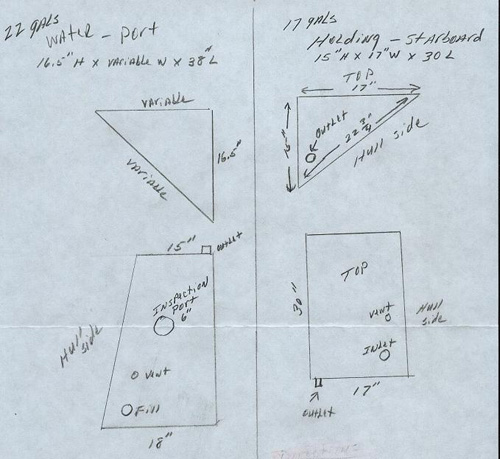
Construction directions:
1. Even though I have provided dimensions in this article, it would be wise to do as I did and start with a cardboard mock up of the tanks. This will insure a good fit after construction is complete.
2. Begin by cutting the top, inboard side and the ends of the tank.
The actual dimension of the hull side (hypotenuse) of the water tank will vary with your actual top and inboard side dimension…so, best to leave until step #3 is complete. If you do not make the holding tank any larger than my dimensions, it will turn out to be rectangular on the hull side. In both cases I cut the hull side out by laying the glued up box on top of the plywood sheet and tracing around. I think this insures the best fit.
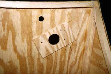
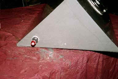
The pictures below show the beginnings of the water tank (hull side is not in place):
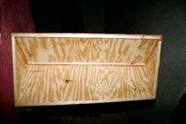
3. With thickened resin, glue and screw the quarter round cleats in place and glue and screw the top, side and ends together.
Pictures below show this process (note that ¾ inch parting stock was used for cleats – quarter round is better):

4. Cut out plywood stiffeners for the fittings and attach to inside of tank with epoxy and screws.
Picture below shows this for the fill port on the water tank:
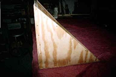
5. Cut out hull side of tank. Best to lay box on top of plywood sheet and trace around for exact dimensions. Remember that the water tank hull side will not be a rectangle because the forward end of the box is smaller than the aft end (to accommodate hull narrowing).
6. Cut holes for the inlet, outlet and vent. For water tank also cut out for inspection port. Cut through both the tank plywood and the stiffeners.
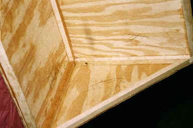
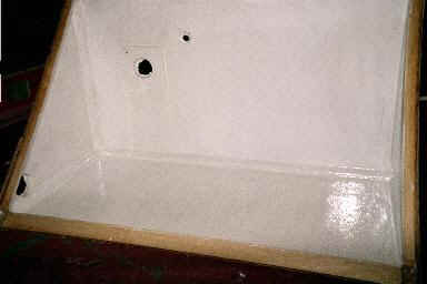
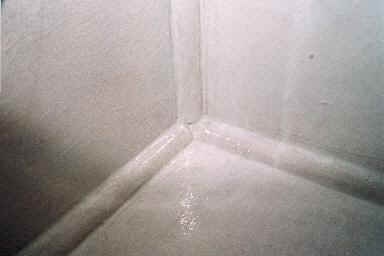
7. Put three to four coats of white pigmented epoxy on the inside of the tank as well as the inside surface of the top. The white pigment will make it easier to see the scum when it comes time to clean out the tank. Be certain to epoxy the raw edges of the cutouts for the fittings. Make certain that all seams (inside and out) are filled with resin. If you do not wait until the epoxy is completely set before adding additional coats you will not need to sand between coats.
Pictures of inside of holding tank (note use of quarter round):
8. Attach hull side of tank with thickened epoxy and screws.
9. Wet out all edges of the tank exterior and put on 4” strips of fiberglass cloth wrapped around the edges.
10. Thoroughly saturate the fiberglass strips and let dry to tacky.
11. Put two coats of epoxy on all exterior surfaces.
12. Adjust dimensions of fitting ports with a wood rasp so that fittings fit tightly.
13. When epoxy is dry (not tacky to touch) finish sand all exterior surfaces with 220 grit paper.
14. Put on two coats of Interlux BilgeCoat (available from West Marine).
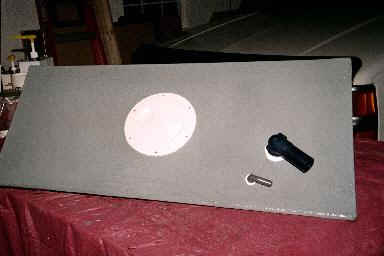
15. Install fittings with polysulfide caulk.
Final outcome of water tank should look like this:
16. Fill with water – cross fingers and hope nothing leaks!
17. Install in boat. Some adjustments will need to be made to get the water tank on a slight angle so that most of the water can be pumped out as it is used. Some adjustment may be needed between tank and hull in order for tank to fit tightly in space.
